Variable-speed wind energy conversion systems (WECS) were developed to solve exactly that problem. By continuously adjusting rotor speed to match the wind, they extract significantly more energy than their fixed-speed predecessors across all wind conditions.
This article covers how variable-speed WECS work, the key components and generator technologies involved, their performance advantages, and how they fit into applications ranging from utility-scale wind farms to off-grid microgrids.
Key Takeaways
- Variable-speed WECS continuously adjust rotor speed to maintain peak aerodynamic efficiency across changing wind conditions
- NREL field tests recorded 2.3% to 5% annual energy production gains over fixed-speed operation
- Three generator architectures dominate: DFIG (partial converter), PMSG (full converter), and SCIG (limited variable-speed range)
- PMSG-based direct-drive systems suit remote deployments where maintenance access is restricted
- Paired with GridGenius EMCS, variable-speed wind turbines can achieve up to 90–100% renewable penetration in isolated microgrids
What Is a Variable-Speed Wind Energy Conversion System?
A Wind Energy Conversion System (WECS) captures wind's kinetic energy and converts it into electricity through a turbine-generator-converter chain. The "variable-speed" distinction is specific: rotor speed continuously adjusts to match changing wind conditions, unlike fixed-speed designs that hold a single set speed regardless of wind conditions.
The Three Operating Regions
Variable-speed control plays out differently depending on wind intensity. NREL identifies three distinct regions:
- Below-rated region — The turbine pursues maximum energy capture by operating at the optimal power coefficient (Cp). This is where variable-speed control delivers its greatest advantage.
- Rated power region — Once wind speed reaches the design point, rotor speed is regulated to hold output constant and protect equipment.
- Above-rated/cut-out region — At very high wind speeds, power is limited or the turbine shuts down entirely to prevent overload.
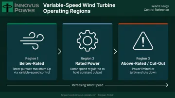
Variable-speed control delivers its greatest gains in the below-rated region — a fixed-speed machine operating there simply cannot track optimal Cp, and that uncaptured energy is gone. Understanding how WECS are classified helps clarify where variable-speed designs fit within the broader technology landscape.
How WECS Are Classified
Variable-speed WECS can be characterized along three main dimensions:
- Turbine axis: Horizontal-axis (HAWT) or vertical-axis (VAWT) — the vast majority of commercial installations are HAWTs
- Power scale: Low (residential/small commercial), medium, and high (utility-scale multi-MW)
- Rotational speed control: Fixed-speed or variable-speed — the core distinction this article addresses
Fixed-Speed vs. Variable-Speed WECS: Why the Difference Matters
The Fixed-Speed Efficiency Problem
A fixed-speed turbine achieves its peak aerodynamic efficiency — the optimal lift-to-drag ratio — at exactly one wind speed. At every other speed, energy capture is suboptimal. When wind gusts arrive, they translate directly into sudden torque spikes in the drivetrain, forcing rotor designs that prioritize structural survivability over energy capture.
Variable-speed operation solves this by continuously varying rotor speed to maintain the optimal tip-speed ratio (TSR) — the ratio of blade tip speed to wind speed. NREL research on the AWT-26 turbine identified an optimal TSR of 9 across a rotor speed range of 32 to 58 rpm, demonstrating how the turbine can chase peak Cp across a wide operating envelope rather than at a single point.
Gust Absorption: From Mechanical Stress to Electrical Energy
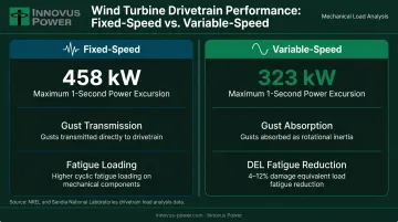
In a fixed-speed turbine, a wind gust hits the drivetrain immediately. In a variable-speed machine, the rotor accelerates slightly, storing the energy as rotational inertia and converting it to electricity gradually. NREL's field testing showed this reduced maximum one-second average power excursions to 323 kW, compared with 458 kW for constant-speed operation on the same turbine.
This directly affects component longevity. NREL found that variable-speed Cp-maximization strategies reduced drivetrain cyclic loading — though one test configuration showed increased tower fatigue loading, confirming that the balance of benefits depends on the specific control strategy and turbine design.
The Role of Power Electronics
Variable-speed control depends entirely on the power converter to function. An AC-DC-AC converter decouples the generator's variable-frequency output from the fixed-frequency grid using Insulated Gate Bipolar Transistors (IGBTs), letting the rotor spin at whatever speed the control system targets.
IEEE reported IGBT-based inverters available at ratings up to 2 MW for wind applications, and advances in semiconductor capacity have been a key reason for variable-speed adoption at commercial scale.
Core Components of a Variable-Speed WECS
Rotor and Pitch Control
The rotor — hub plus blades — is the primary energy-capture element. Variable-speed turbines use active pitch control: a computer-actuated mechanism that rotates blade angle to regulate rotor speed and power output, particularly when wind speeds exceed the turbine's rated design threshold. This contrasts with fixed-speed stall-regulated rotors, which rely on passive aerodynamic stall to limit power.
Drivetrain: Gearbox and Direct-Drive Options
The main low-speed shaft connects the rotor to the gearbox, which steps up rotational speed to match generator requirements. Alternatively, direct-drive (gearless) configurations eliminate the gearbox entirely, reducing mechanical complexity and removing one of the more maintenance-intensive components from the system. Research from DOE/NREL points toward medium-speed permanent-magnet generators as a practical middle ground — retaining some gearing to reduce generator size while avoiding the complexity of full multi-stage gearboxes.
Power Converter (AC-DC-AC)
The two-stage conversion process:
- Machine-side converter (rectifier): Converts the generator's variable-frequency AC output to DC
- Grid-side inverter: Converts DC back to grid-compatible AC at fixed voltage and frequency
This architecture fully decouples generator speed from grid frequency — the defining feature that makes variable-speed operation practical.
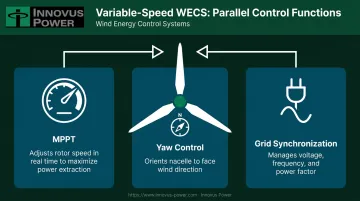
Control System: MPPT, Yaw, and Grid Sync
Three control functions run in parallel:
- MPPT (Maximum Power Point Tracking): Adjusts rotor speed setpoints in real time to maximize power extraction in below-rated winds
- Yaw control: Orients the nacelle to face the wind direction
- Grid synchronization: Manages voltage, frequency, and power factor compliance
Together, these systems work in concert to keep a variable-speed turbine operating at peak efficiency across a wide range of wind conditions.
Generator Technologies in Variable-Speed WECS
Generator choice has major downstream implications for converter sizing, maintenance requirements, and deployment suitability.
Doubly-Fed Induction Generator (DFIG)
The DFIG stator connects directly to the grid, while the rotor connects via slip rings to a partial-scale power converter — typically rated at only 20-30% of total turbine capacity for a speed range of 0.7 to 1.3 per unit, according to a 2022 Energies paper. This smaller converter is the DFIG's primary cost advantage.
The tradeoff: slip rings, brushes, and bearing degradation from stray currents all require ongoing maintenance. DFIG suits large grid-connected applications where converter cost matters and skilled maintenance teams are accessible.
Permanent Magnet Synchronous Generator (PMSG)
PMSG uses a full-scale power converter handling 100% of output power, completely decoupling the generator from the grid. Key advantages:
- No external excitation current required
- No slip rings or brushes
- High efficiency and reliability
- Compatible with direct-drive (gearless) configurations
The full converter costs more upfront than a DFIG's partial converter. In practice, the removal of slip rings and gearbox maintenance offsets that premium quickly — especially in remote or offshore deployments where service calls are expensive. PMSG has become the preferred architecture wherever maintenance access is limited or reliability requirements are non-negotiable.
Squirrel Cage Induction Generator (SCIG)
The SCIG is the simplest and most cost-effective generator type, traditionally used in fixed-speed machines. It can be adapted for limited variable-speed range via partial converters, and still accounts for a share of installed wind capacity globally. Its limited speed range and reactive power consumption, however, make it a poor fit for variable-speed applications.
Selection Summary
Each generator type occupies a distinct performance and cost niche. The table below summarizes the tradeoffs:
| Generator | Converter Size | Maintenance Needs | Best Fit |
|---|---|---|---|
| DFIG | ~20–30% of rating | Moderate (slip rings) | Large grid-connected farms |
| PMSG | Full-scale (100%) | Low (no slip rings/gearbox) | Remote, off-grid, offshore |
| SCIG | Partial or none | Low | Legacy/low-cost fixed-speed |
Efficiency and Performance Advantages of Variable-Speed WECS
Annual Energy Production Gains
NREL's field testing of the fixed-pitch variable-speed AWT-26 turbine recorded 2.3% to 5% annual energy production improvement over fixed-speed and soft-stall operation. The gain comes from maintaining near-optimal Cp across a broader wind speed range rather than at a single design point. For a wind farm operating over decades, even a 3% improvement in AEP compounds into substantial additional revenue.
Reduced Mechanical Loads
Gust absorption is one of the most consequential mechanical benefits of variable-speed operation. Rather than transmitting wind spikes directly through the drivetrain, variable-speed systems convert that energy electrically, reducing fatigue cycling on blades, shafts, and structural components. Sandia National Laboratories research on a 3.4 MW turbine model found active load control strategies reduced fatigue damage equivalent load (DEL) by 4-8% below rated wind speed and 8-12% above rated wind speed. PMSG-based direct-drive configurations push this further by eliminating gearbox servicing entirely.
Power Quality and Grid Services
Modern variable-speed WECS produce power at near-unity power factor and reduce the need for reactive power compensation. Beyond basic power quality, they can deliver:
- Low-Voltage Ride-Through (LVRT): Remaining connected and actively supporting voltage during grid dips, rather than disconnecting and deepening the disturbance
- Synthetic inertia: Providing frequency response during grid events, a function NREL confirmed can measurably stabilize system frequency response
- Reactive power support: Active management of voltage at the point of interconnection
These capabilities make variable-speed machines more capable grid participants than fixed-speed alternatives. The same advantages apply in off-grid microgrid applications where frequency and voltage stability depend on the generators present.
Innovus Power's variable-speed generator technology applies these same principles in its microgrid generation systems, delivering up to 50% greater efficiency across all load levels. That advantage is especially pronounced in low-load continuous operation — a common scenario in remote or off-grid deployments where fixed-speed machines run inefficiently and drive up fuel costs.
Variable-Speed WECS in Microgrid and Real-World Applications
Utility-Scale and Grid-Connected Wind
Large onshore and offshore wind farms represent the primary deployment environment for multi-MW variable-speed turbines. Global offshore wind capacity reached 68,258 MW by end-2023, with offshore sites capturing stronger, more consistent winds — and higher capacity factors — at the cost of greater installation and maintenance complexity. Variable-speed turbines with PMSG direct-drive architectures are increasingly favored offshore, where access for gearbox maintenance is expensive and logistically difficult.
Remote, Off-Grid, and Islanded Applications
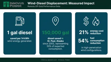
Variable-speed WECS are particularly well-suited for locations where grid connection is unavailable or prohibitively expensive. The economics are direct: every kilowatt-hour of wind generation displaces diesel fuel. Key figures from NREL's Alaska wind-diesel research illustrate the impact:
- 1 gallon of diesel saved per 14 kWh of wind generation
- St. Paul, Alaska project saved an estimated 150,000 gallons since 2005 — about 50% of expected consumption without wind
- High-penetration renewable configurations produced 21% energy cost reduction and 54% fuel consumption reduction in NREL community modeling
For these deployments, PMSG-based direct-drive turbines are the preferred choice. They eliminate gearboxes and slip rings, reducing the maintenance burden to a level that fits communities where technical support may be hours away.
Cold-climate sites introduce additional design requirements. Natural Resources Canada identifies blade icing, increased rotor loads, and cold-weather shutdown risks as factors that require specific turbine design accommodations.
Integration Into Intelligent Microgrids
A variable-speed wind turbine generates maximum value when embedded in a smart microgrid that can balance its variable output against battery storage, backup generation, and solar in real time. RMI's island microgrid case studies found that 12 wind turbines paired with a 100 kWh battery system could provide up to 90% of electricity during high-wind periods.
Achieving that kind of penetration consistently requires an energy management layer that can act on real-time conditions across all sources. Innovus Power's GridGenius EMCS manages variable-speed wind alongside solar, stored energy, and dispatchable generation to achieve up to 90–100% renewable penetration in deployments serving remote communities, military bases, and commercial and industrial customers. Its vendor-agnostic architecture integrates third-party wind turbines within a broader multi-source microgrid without locking operators into proprietary hardware.
Frequently Asked Questions
How do you size a wind turbine for a remote site or commercial facility?
Sizing depends on two variables: your site's annual energy demand and its average wind speed. The DOE's Small Wind Guidebook provides a practical starting framework — a 5 to 15 kW turbine can meaningfully offset smaller facility loads, while remote communities and commercial sites typically require multi-turbine arrays integrated with storage and backup generation to meet firm power requirements.
What is the difference between fixed-speed and variable-speed wind turbines?
Fixed-speed turbines operate at a single rotor speed and achieve peak efficiency only at one specific wind speed. Variable-speed turbines continuously adjust rotor speed to maintain optimal aerodynamic efficiency across a wide range of conditions, and they absorb gusts as electrical energy rather than drivetrain mechanical stress.
What generator types are most commonly used in variable-speed WECS?
The three main types are DFIG (partial-scale converter, suited for large grid-connected farms), PMSG (full-scale converter including direct-drive options, preferred for remote and offshore applications), and SCIG (limited variable-speed range, primarily legacy installations). DFIG and PMSG dominate modern variable-speed deployments.
What are cut-in and cut-out wind speeds, and why do they matter?
Cut-in speed is the minimum wind speed at which a turbine starts generating power; Vestas's 4 MW platform, for example, cuts in at 3 m/s. Cut-out speed is the maximum safe operating speed before shutdown — the same platform cuts out at 22.5 to 24.5 m/s. Variable-speed turbines capture usable energy across the full operating range between these two thresholds, rather than peaking at a single fixed point.
Can variable-speed WECS operate effectively in off-grid or remote locations?
Yes, particularly PMSG-based direct-drive configurations that minimize maintenance requirements. When paired with battery storage and an intelligent EMCS within a microgrid architecture, variable-speed WECS can deliver reliable power at a high renewable fraction with no utility grid connection required.
How do variable-speed wind turbines integrate with microgrids?
Variable-speed WECS connect to microgrids through their power converter, which allows real-time output control. An EMCS coordinates wind generation with storage, solar, and other sources to maintain stable voltage and frequency, prevent curtailment, and maximize renewable penetration even in fully islanded operation.