Introduction
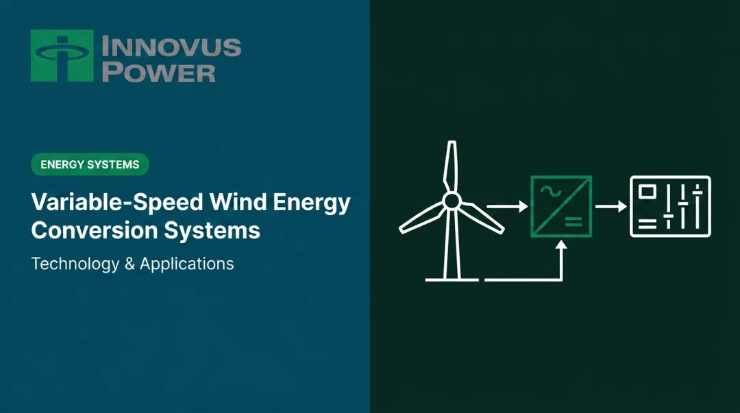
Wind turbines, run-of-river hydro plants, and distributed cogeneration systems all share one stubborn problem: the prime mover never runs at a perfectly constant speed. Wind gusts. Water flow drops at the end of dry season. Engine load shifts. Yet the grid demands a rock-steady output frequency — 50 or 60 Hz, every second.
Asynchronous (induction) generators are the dominant technology for handling this mismatch. A 2022 multi-MW wind generator review reports that doubly-fed induction generators (DFIGs) account for more than 80% of the generator market in that segment, driven by one core advantage: rotor speed doesn't have to be mechanically locked to the grid.
Variable rotor speed control is the mechanism that decouples rotor speed from grid frequency. This guide explains the full operating sequence — from the slip-frequency relationship through rotor current adjustment to stable grid output — so engineers and system designers can make informed decisions about generator selection, converter sizing, and control architecture.
Key Takeaways
- Asynchronous generators produce AC power when the rotor spins faster than the stator's synchronous magnetic field — the speed difference is called slip
- Variable rotor speed control adjusts rotor excitation frequency to compensate for mechanical speed changes, keeping stator output at grid frequency
- DFIGs use a partial-rated rotor converter (typically ~25% of system power) to enable ±33% speed range operation while delivering constant-frequency output
- This approach reduces drivetrain mechanical stress, improves energy capture from variable prime movers, and enables reactive power control
- Platforms like GridGenius EMCS coordinate variable-speed generator dispatch in real time, enabling up to 90–100% renewable energy penetration without curtailment
What Is an Asynchronous Generator with Variable Rotor Speed Control?
An asynchronous generator produces AC electricity when its rotor is driven faster than the stator's rotating magnetic field. Unlike a synchronous generator, which must match rotor speed precisely to grid frequency before connecting, the induction machine's rotor speed is never rigidly tied to the electrical output. That mechanical decoupling is the defining characteristic of the technology.
The Problem with Fixed-Speed Operation
Standard squirrel-cage induction generators operate within a very narrow speed band. NREL's wind turbine modeling documentation describes fixed-speed induction generators as operating with only small slip, around 1–2% above synchronous speed. Any significant deviation in prime mover speed converts directly into power fluctuation, torque pulsations, and flicker rather than a change in output frequency (the grid maintains that).
The machine is stiff, simple, and cheap, but aerodynamically and hydraulically wasteful.
Variable rotor speed control was developed to solve this. By decoupling rotor mechanical speed from stator output frequency, a generator can accept a wide range of input speeds and still deliver grid-quality power.
What Variable Speed Control Is (and Isn't)
Three generator types define the landscape:
- Squirrel-cage induction generator (SCIG): Brushless, robust, no external rotor connections, but limited to that narrow fixed-speed band
- Doubly-fed induction generator (DFIG): Uses a wound rotor with external connections to a power electronic converter, enabling controlled wide-range variable speed operation
- Synchronous generator: Requires precise speed matching to grid frequency before synchronization — no inherent variable-speed capability
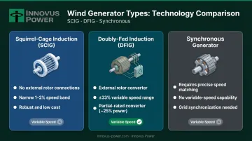
IEEE's foundational DFIG paper by Muller, Deicke, and De Doncker reports that DFIG systems allow a ±33% speed range around synchronous speed, using a rotor-side converter rated at only about 25% of total system power. That partial-rated converter is what makes DFIGs economically attractive: wide-range variable speed operation without paying for a full-nameplate power converter.
Why This Matters Now
Variable-speed operation lets a generator track the optimal torque point as prime mover conditions change, maximizing the power coefficient (Cp) of a wind rotor or the hydraulic efficiency of a turbine runner at varying flow rates. NREL describes this as "attempting to maximize energy capture by operating at maximum power coefficient over as broad an RPM range as possible."
The practical gains extend well beyond energy capture:
- Reduces mechanical loading on gearboxes, cutting long-term maintenance costs
- Smooths torque delivery, lowering structural fatigue on drivetrain components
- Improves overall system efficiency across a broader operating range than fixed-speed designs allow
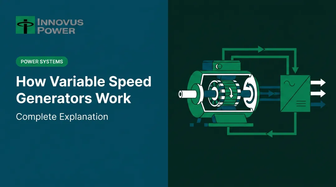
How Variable Rotor Speed Control Works
Variable rotor speed control doesn't prevent speed variation — it accommodates it. The control system continuously adjusts rotor excitation so that the combined effect of mechanical rotor rotation and the rotor's magnetic field always produces a stator output at the target grid frequency.
Activation: How the System Starts
In a grid-connected DFIG:
- Stator connects directly to the utility grid — the grid magnetizes the machine at grid frequency
- The prime mover accelerates the rotor above synchronous speed (negative slip), transitioning the machine from motor-like startup into generator operation
- The rotor-side converter begins injecting controlled AC current into the rotor windings via slip rings
- A speed-measuring device feeds rotor RPM data continuously to the converter's control circuit — this feedback loop is the trigger for all subsequent frequency compensation
Core Operation: The Slip-Frequency Relationship
IEEE defines the fundamental relationship as:
ω_R = ω_s − ω_mech and s = (ω_s − ω_mech) / ω_s
In practical terms, the rotor electrical frequency is:
f_rotor = s × f_stator
Or equivalently: f_rotor = f_stator − (n × p / 60)
where n is rotor speed in RPM and p is the number of pole pairs.
What this means physically:
- Sub-synchronous operation (rotor below synchronous speed): The control circuit increases rotor current frequency, causing the rotor's magnetic field to rotate faster relative to the rotor body — compensating for the slower mechanical rotation and restoring the stator field to grid frequency. Per the IEEE source, active power is circulated from the grid into the rotor circuit in this mode.
- Super-synchronous operation (rotor above synchronous speed): Rotor current frequency is reduced and phase sequence reverses — the rotor field still rotates at the correct net synchronous speed. The converter captures slip power from the rotor and feeds it back to the grid, improving overall efficiency.
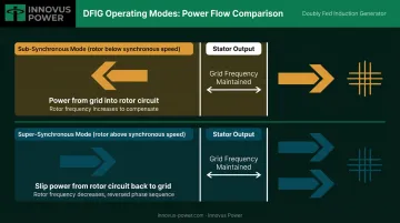
The transition between these two states must occur smoothly, and the phase sequence of rotor current reverses automatically at the crossover point.
Regulation: Continuous Control in Operation
The converter's control architecture manages two separate but linked functions.
Speed and active power are managed through rotor current frequency:
- Speed sensor monitors rotor RPM in real time
- Control circuit calculates required rotor current frequency using the slip-frequency equation
- IGBT-based back-to-back PWM converters adjust rotor current accordingly
- IEEE describes vector control as the method used to decouple active and reactive power control
Voltage and reactive power are managed through rotor current magnitude:
- Rotor current magnitude (not just frequency) controls terminal voltage and reactive power exchange
- When load increases and terminal voltage drops, the control circuit detects this via voltage feedback and increases rotor current magnitude to restore voltage
- This dual-axis control — frequency for active power, magnitude for reactive power — allows DFIGs to meet power quality requirements without a separate voltage regulator
A single rotor-side converter handles both functions simultaneously, which is what makes this architecture efficient enough for demanding grid-tied and off-grid applications.
Output: What the System Delivers
Regardless of whether the rotor runs sub- or super-synchronously, the stator delivers AC power at grid frequency and voltage. The output integrates directly into the grid without additional AC/DC/AC conversion on the stator side.
Off-grid operation changes this picture. Capacitor banks replace the grid's reactive excitation supply, and the control system must manage voltage and frequency stability internally — a significantly more demanding task than grid-tied operation.
Where Variable-Speed Asynchronous Generators Are Used
Grid-Connected Wind Turbines
This is the dominant application. Variable wind speeds make fixed-speed operation genuinely inefficient — torque variations that a DFIG absorbs electrically become power fluctuations and drivetrain stress in a fixed-speed SCIG. At the hundreds-of-kilowatt to multi-megawatt scale, the converter cost is justified by improved energy capture and reduced mechanical wear.
GWEC reported 1,299 GW of global installed wind power in 2025, with 165 GW of new capacity added. The majority of that installed base uses DFIGs or full-converter configurations — both relying on the same underlying principle of electrical speed decoupling.
Micro-Hydro and Run-of-River Systems
Run-of-river installations face seasonal and daily flow variations that change turbine runner speed continuously. A 2017 Elsevier paper notes that squirrel-cage induction machines are used extensively as generators for micro-hydropower due to their robustness, while variable-speed configurations using back-to-back converters are evaluated for their ability to track maximum power point across varying flow rates.
The efficiency advantage is most apparent at partial flow — where a fixed-speed machine must either throttle the turbine or waste energy, a variable-speed configuration adjusts rotor speed to hold the runner near its best efficiency point year-round.
Intelligent Microgrids
In remote and islanded microgrids — serving mining operations, remote communities, military bases, and industrial facilities — variable-speed generators must coordinate with battery storage, solar, and variable loads across shifting demand cycles. Generator-level control alone can't manage those interactions.
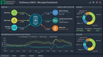
Platforms like Innovus Power's GridGenius EMCS coordinate variable-speed generator dispatch in real time. By managing the interactions between generation assets, storage, and load, GridGenius enables up to 90–100% renewable energy penetration without sacrificing power quality. Innovus Power's variable speed generators are designed to deliver up to 50% superior efficiency at all load points — the direct result of matching generator speed to the prime mover's efficiency optimum rather than locking it to a fixed mechanical speed.
Conclusion
Variable rotor speed control in asynchronous generators works through a continuous, real-time feedback loop. Measure rotor speed, calculate the required slip, inject rotor current at the correct frequency and magnitude — and the stator delivers grid-frequency power regardless of what the wind, water, or engine is doing mechanically.
Engineers who understand how slip, rotor frequency adjustment, and PWM vector control interact can:
- Select the right generator topology (SCIG vs. DFIG) for a given prime mover profile
- Size the rotor-side converter correctly — typically around 25% of system nameplate power
- Define the operating speed range and determine where sub- and super-synchronous transitions occur
- Specify appropriate reactive power and voltage control requirements
For system designers integrating variable-speed generators into microgrids, generator-level control is only one layer. Coordinating that generator with storage, renewables, and variable loads requires an energy management control system (EMCS) that handles dispatch logic, frequency response, and renewable curtailment avoidance in real time — the kind of orchestration that separates a collection of components from a functioning microgrid.
Frequently Asked Questions
How does an asynchronous generator work?
An asynchronous (induction) generator produces AC electricity when a prime mover drives its rotor above synchronous speed. The speed difference (called slip) induces currents that transfer real power to the grid. Reactive excitation is supplied by the grid itself, or by external capacitor banks in stand-alone systems.
What is the speed of an asynchronous generator?
As a generator, an induction machine runs slightly above synchronous speed (negative slip); as a motor, slightly below (positive slip). Synchronous speed is determined by grid frequency and pole count — for example, a 4-pole machine on a 60 Hz grid has a synchronous speed of 1,800 RPM (n_s = 120f/P).
What is slip in an asynchronous generator and why does it matter?
Slip is the percentage difference between rotor speed and synchronous speed. In generator operation, slip is negative (rotor faster than the field), and its magnitude determines active power output. Controlling slip is the core mechanism through which variable rotor speed control regulates power delivery.
What is the difference between a doubly-fed and a squirrel-cage asynchronous generator?
A squirrel-cage induction generator has a brushless rotor with no external connections and operates within only about 1–2% of synchronous speed. A DFIG uses a wound rotor connected to an external power electronic converter, enabling ±33% variable speed operation (per IEEE) while maintaining stable output frequency.
Can an asynchronous generator operate off-grid in stand-alone mode?
Yes, but it requires an external capacitor bank across the stator terminals to supply reactive power. Voltage and frequency stability in off-grid mode depend on capacitance value, load type, and rotor speed — and are more complex to manage than in grid-connected operation.
What are the main advantages of variable rotor speed control?
Key advantages include:
- Broader speed range — maximizes energy capture from variable prime movers
- Reduced drivetrain stress — speed fluctuations are absorbed electrically, not mechanically
- Independent reactive power control — improves power quality in grid-connected and microgrid applications