Introduction
When solar panels and wind turbines power a DC microgrid, the physics get complicated fast. Renewable output fluctuates with clouds and wind gusts, while loads switch on and off unpredictably. Parallel converters, without coordination, fight each other through circulating currents. For remote communities, mining sites, and mission-critical facilities, that's not a theoretical risk: uncontrolled voltage swings can trigger shutdowns with no utility grid to catch the fall.
The DC microgrid market was estimated at USD $6.56 billion in 2024, projected to grow at 15.35% CAGR through 2032. That growth is driven by one core advantage: DC systems eliminate AC-DC conversion stages, avoid synchronization and reactive power challenges, and integrate batteries and solar PV more directly than AC architectures.
The hardware advantage only holds if the control strategy keeps pace. This guide covers how hierarchical DC microgrid control works — from local converter loops to system-wide optimization — including droop control, secondary voltage restoration, tertiary dispatch, and what it takes to maintain stability at high renewable penetration.
Key Takeaways
- DC microgrids rely on three nested control layers, each operating at a different speed and scope to manage voltage, load sharing, and energy dispatch
- Droop control enables communication-free load sharing among parallel converters but introduces voltage deviation under load
- Secondary voltage restoration corrects droop-induced sag without disrupting load sharing
- Constant power loads (CPLs) create negative impedance that reduces system damping — a critical stability risk in converter-heavy sites
- Adaptive droop and intelligent EMCS platforms enable high renewable penetration with tighter voltage regulation
What Is a DC Microgrid System and Why Control Matters
A DC microgrid is a localized power system where distributed energy sources — solar PV, wind, battery storage, and generators — connect to a common DC bus through power converters. The U.S. Department of Energy defines a microgrid as "a group of interconnected loads and distributed energy resources within clearly defined electrical boundaries that acts as a single controllable entity" that can operate either grid-connected or in islanded mode.
Compared to AC microgrids, DC systems offer several structural advantages:
- No reactive power compensation or power factor correction required
- No synchronization between parallel sources
- Fewer conversion stages for battery storage and PV integration
- Lower conversion losses in DC-dominant load environments
Why Control Is the Central Challenge
Without coordinated control, even properly specified hardware fails. Unmanaged systems run into predictable problems:
- Parallel converters with mismatched output voltages generate circulating currents that waste capacity and stress equipment
- Bus voltage drifts as load demand shifts
- Renewable intermittency triggers rapid voltage swings
- Storage assets charge and discharge without respecting state-of-charge limits
The core control objectives in any DC microgrid are:
- Maintain DC bus voltage within acceptable operating limits
- Share load current proportionally among parallel sources
- Manage storage state-of-charge within operational boundaries
- In grid-tied systems, regulate power flow at the point of interconnection
Achieving all four simultaneously — across changing loads and variable renewable output — requires a control architecture designed for that complexity from the start, not patched together after the hardware is in place.
How DC Microgrid Control Works: The Three-Level Hierarchical Framework
The standard framework for DC microgrid control organizes functions into three nested layers, each operating at a different speed and scope. All three must work in coordination — a gap at any layer propagates instability upward or downward.
Primary Control: Local Converter Regulation
Primary control is the fastest layer, running locally within each converter. It uses nested control loops:
- Inner current loop — controls inductor current, responds fastest
- Outer voltage loop — controls converter output voltage, responds slower than the current loop
Both loops use PI (proportional-integral) controllers. The inner loop must respond faster than the outer to prevent loop interaction and instability. That timing hierarchy is fixed by design and cannot be reversed without introducing instability.
Droop control handles load sharing at this layer. Each converter inserts a virtual droop resistance that creates a load-dependent voltage offset: as output current increases, output voltage decreases proportionally. When two parallel converters have matched droop resistances, they automatically redistribute current during a load step with no inter-converter communication required.
This decentralized behavior is one of droop control's key practical advantages.
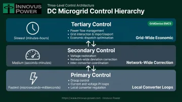
Secondary Control: Voltage Restoration
Droop control's load sharing comes at a cost: bus voltage sags under load in proportion to the droop resistance. Secondary control addresses this with a shared voltage restoration loop common to all converters.
The secondary controller compares actual DC bus voltage to the reference setpoint and generates a correction signal (the restoration voltage) that feeds into every primary control loop simultaneously. This corrects the steady-state voltage error without disrupting the current-sharing behavior that droop established.
Secondary control is slower than primary control and operates network-wide rather than per-converter. It handles steady-state correction, not transient response.
Tertiary Control: Power Flow and Grid Interaction
Tertiary control is the supervisory layer. In grid-tied systems, it manages import/export decisions based on load requirements, available generation, and economic dispatch logic. Key tertiary functions include:
- Coordinating with Energy Management Systems for grid connection and disconnection
- Governing transitions between grid-connected and islanded operating modes
- Managing economic dispatch across available generation sources
Mode transitions are the highest-risk events at this layer. A poorly timed switch between grid-connected and islanded operation can cause voltage excursions that the primary and secondary layers cannot catch fast enough to prevent a load disruption.
DC Bus Voltage Management: Droop Control Strategies Explained
Droop control is the primary mechanism for sharing load among parallel converters in a DC microgrid — without it, small mismatches in converter output voltage cause large, uncontrolled current imbalances. Two methods are used in practice, and the choice between them affects control complexity, dynamic behavior, and how secondary voltage restoration integrates.
V-I Droop (Impedance Method)
V-I droop is the conventional approach. A virtual droop resistance (R_droop) is added to the voltage control loop. The product of output current and R_droop is subtracted from the voltage reference, creating a load-dependent voltage sag that forces current sharing among parallel converters.
The core design trade-off: a larger R_droop produces faster, more proportional current sharing but at the cost of greater voltage deviation from the setpoint. Designers must balance these competing requirements based on the application's voltage tolerance band.
For industrial DC systems, VDE SPEC 90037 specifies a 540 V/650 V nominal operating range of 400–800 V, with disconnection thresholds below 400 V or above 880 V in less than 1 ms and a maximum voltage rate of change of 13 V/ms. These are concrete engineering constraints — not generic ±5% or ±10% rules of thumb.
I-V Droop (Admittance Method)
I-V droop replaces the voltage PI controller with a proportional multiplier (k = 1/R_droop). The voltage error (reference minus actual) is multiplied by k to produce the current reference for the inner current loop. The strictly proportional structure eliminates integral windup, which improves response speed in battery-dominant topologies and fast-switching load applications where integral lag creates instability.
Secondary Restoration Integration
Both droop methods accumulate voltage error over time, requiring a secondary layer to restore the bus to its nominal value. Two approaches handle this:
- Secondary restoration loop: Adds a correction voltage (v_res) to the primary voltage reference, offsetting the droop-induced sag while preserving load sharing ratios among converters.
- Constant DC voltage control: Assigns a single designated source — typically a battery storage system or an AC/DC interlinking converter — to hold the bus voltage fixed, while all other sources operate in constant power mode. This is the more common architecture in hybrid AC-DC microgrid topologies.
Stability Challenges in DC Microgrids and How to Overcome Them
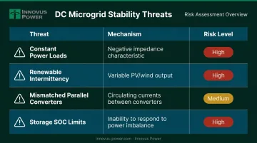
The Four Core Stability Threats
| Threat | Mechanism | Risk Level |
|---|---|---|
| Constant power loads (CPLs) | Negative incremental impedance reduces system damping | High — can cause oscillation or voltage collapse |
| Renewable intermittency | Variable PV/wind output creates rapid bus voltage fluctuations | High in storage-limited systems |
| Mismatched parallel converters | Parameter differences cause unequal current sharing and circulating currents | Medium |
| Storage SOC limits | Storage at capacity limits cannot respond to power imbalances | High in extended islanded operation |
Active Damping Techniques
CPL instability is a primary concern at converter-heavy industrial sites. Loads regulated by downstream converters present negative resistance to the DC bus, reducing overall system damping. Two software-based active damping approaches address this without adding passive components:
- State feedback control — oscillating voltage and current signals are measured and fed back through the converter's duty cycle, adding virtual damping to the system
- High-pass filtered voltage feedforward — filters the output voltage signal into the outer voltage loop to compensate damping without shifting the steady-state operating point
An IEEE conference study on low-pass filter methods showed that introducing an LPF into the droop control link reduces source converter output impedance, improving the stability margin against CPL loads. Research validated that active damping with continuous-time MPC achieved voltage restoration in 30–50 ms with only a 2.3 V deviation for a 300 W load step.
Energy Storage Coordination for Voltage Stability
Distributed energy storage connected through bidirectional DC-DC converters serves a dual role:
- Absorbs surplus power or supplies deficit power in real time, smoothing renewable output fluctuations before they reach the bus
- Holds DC bus voltage stable during transients through constant-DC-voltage control mode
Storage that reaches upper or lower SOC limits simply cannot respond to power imbalances — and that gap will show up as a bus voltage deviation. Control systems must incorporate SOC-aware operating-mode constraints that keep storage assets within their functional range. This means transitioning between voltage-forming and power-dispatch modes based on SOC thresholds, ahead of those limits.
Advanced and Adaptive Control for High Renewable Penetration
Adaptive Droop Control
Conventional droop uses fixed coefficients, which works well for stable, predictable systems but poorly under variable renewable conditions. Adaptive droop dynamically adjusts droop coefficients based on real-time inputs like SOC, renewable output level, or bus voltage deviation.
Fuzzy logic controllers (FLC) are the most common implementation. They adjust virtual resistance values based on multi-variable inputs without requiring precise system models — well-suited to the nonlinear, variable conditions of renewable-heavy microgrids. Studies using an IEEE 9-bus DC microgrid model demonstrated improved voltage regulation under generation uncertainty with FLC-based adaptive droop.
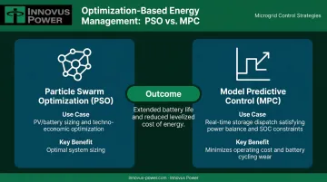
Optimization-Based Energy Management
Higher-level optimization handles energy dispatch decisions that droop control cannot:
- Particle Swarm Optimization (PSO) — used for sizing and techno-economic optimization of PV/battery systems
- Model Predictive Control (MPC) — dispatches storage to satisfy power balance, SOC, and rated power constraints simultaneously while minimizing operating cost, including battery cycling wear
Both methods extend battery life and reduce levelized cost of energy beyond what simple proportional distribution achieves.
Intelligent EMCS Integration
The practical value of these techniques depends on whether they're integrated into a coherent platform. Innovus Power's GridGenius EMCS coordinates droop control, voltage restoration, storage dispatch, and renewable integration across all three hierarchical control layers within one platform.
GridGenius includes dedicated renewable and stored energy optimization software, Virtual Synchronous Generator (VSG) software for grid stability management, and real-time monitoring through PowerView. The system's vendor-agnostic design gives operators flexibility to select converters, storage, and generation technologies based on performance fit — not around any single supplier's constraints.
Selecting the Right DC Microgrid Control Strategy for Your Application
Islanded vs. Grid-Tied: Different Control Priorities
Fully islanded systems (remote communities, Arctic installations, mining sites) must be entirely self-regulating. There's no utility backstop. Robust primary and secondary control, comprehensive SOC-aware storage management, and reliable mode-transition logic aren't optional — they're the difference between a functioning microgrid and a blackout.
Grid-tied commercial and industrial sites can use tertiary control to optimize import/export economics. The grid provides a stability backstop, which shifts design priority toward dispatch optimization and power quality rather than voltage-forming resilience.
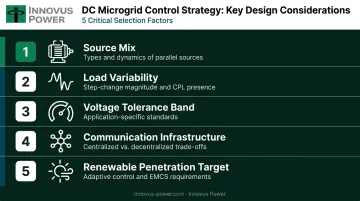
Key Design Considerations
Before selecting a control strategy, evaluate:
- Source mix — number and types of parallel sources (PV, wind, battery, generator) and their dynamic characteristics
- Load variability — step-change magnitudes and frequency, presence of CPL loads
- Voltage tolerance band — application-specific standards (not generic percentages)
- Communication infrastructure — centralized restoration requires reliable communication; fully decentralized droop sacrifices some voltage accuracy for resilience
- Renewable penetration target — higher targets require adaptive control and intelligent EMCS
Why System Design Expertise Matters
Integrating multiple control layers across diverse technologies introduces complexity that doesn't resolve itself at commissioning. Control parameters that work in simulation can interact unexpectedly in the field. The sources of that complexity typically include:
- Converters from different manufacturers with differing dynamic response profiles
- Storage systems with varying electrochemical characteristics and aging behavior
- Renewable sources whose output fluctuates on timescales that stress secondary control loops
Innovus Power brings over 30 years of experience designing vendor-agnostic DC and hybrid microgrids, with proprietary modeling tools that validate control strategy performance before deployment. That pre-deployment validation is what prevents commissioning surprises from becoming operational failures.
Frequently Asked Questions
Are microgrids AC or DC?
Microgrids can be AC, DC, or hybrid AC/DC. DC microgrids are increasingly preferred for applications with significant renewable generation and battery storage because they eliminate AC-DC conversion stages, reduce losses, and avoid synchronization and reactive power challenges.
What is a DC microgrid system?
A DC microgrid is a localized electrical system where distributed energy sources, loads, and storage connect on a common DC bus, managed by power converters and a control system. It can operate independently from the utility grid or in grid-tied mode as a single controllable entity — consistent with the DOE's definition of a microgrid.
What is a microgrid control system?
A microgrid control system is the set of algorithms and hardware managing voltage, load sharing, energy storage, and power flow within the microgrid. It is organized into three levels as defined by IEEE 2030.7: primary (local converter), secondary (voltage restoration), and tertiary (grid interaction and optimization).
What is an adaptive control system for a DC microgrid?
An adaptive control system dynamically adjusts control parameters (such as droop coefficients or dispatch setpoints) in response to changing conditions like renewable output, load shifts, or storage state-of-charge. This improves stability and efficiency compared to fixed-parameter conventional controllers.
What is droop control in a DC microgrid?
Droop control is a decentralized load-sharing technique where each parallel converter reduces its output voltage in proportion to its output current, naturally equalizing current distribution among converters without requiring inter-converter communication.
How does DC microgrid control enable renewable energy integration?
Control systems enable renewable integration by using energy storage coordinated through bidirectional converters to buffer intermittent solar and wind output, while adaptive EMCS algorithms dispatch generation and storage to maintain DC bus voltage stability across variable conditions.